Tag: antenna
21 November 2013 » CCRadio EP portable
CCRadio-EP AM/FM Portable - A Bob Grove What’s New Review
Larry Van Horn, New Products Editor
While it may seem strange that we would be reviewing anything as plebian as an AM/FM portable radio, there is a method to our madness. For several years, GE offered their “Superadio” to the consumer market; it had good sound, sharp AM selectivity, and external antenna connections. The radio sold in the $50-$60 range, and was very popular with domestic AM broadcast DX- ers. When it was discontinued, we had a surge of inquiries for a replacement, but none was to be found. Will the new CCRadio-EP be the answer?
The radio has decent sound, good AM selec- tivity, wide/narrow FM selectivity, and external antenna connectors. It has the traditional, analog, slide-rule tuning dial which may be backlit for night viewing.
Its 4-inch, self-contained speaker delivers room-filling sound with notable bass and clean highs with minimal distortion. Separate bass and treble controls invite custom high/low roll-offs to suit the listener’s preference. If you have a set of stereo headphones, a stereo output jack provides that listening mode as well. There is also a line-in jack in case you have a personal MP3 or other player that you’d like to hear through a larger speaker.
The radio runs on either four D cells (not included) or a 120 VAC/6 VDC wall adapter (included). A snap-up/snap-down carrying handle facilitates transport.
The CCRadio-EP is simple to operate and should appeal to techie types with its unique “Twin Coil Ferrite” AM fine tuning knob. This is an RF peaking adjustment for the antenna input, depending on the frequency being received. It works with both the internal and external antenna.
It appears that the choice of external an- tenna is rather critical, and experimenting with optimum length and placement may be necessary to avoid “swamping” that tuning circuit, as well as avoiding common mode (ground loop) hum. I suspect that a shorter outdoor wire antenna would be better than a long one.
The internal ferrite loop antenna remains in service with the external antenna attached. If you were experiencing electrical noise interfer- ence, it will still be there, hopefully attenuated somewhat by stronger signal strengths brought in by the outdoor wire. It is advisable to attach a ground wire to that respective terminal as well to avoid AC hum and other electrical line noise. If such interference persists, battery operation and/ or relocation of the radio are recommended.
An FM internal/external switch allows selection of an outdoor antenna via a TV-style F connector. The benefits and disadvantages of high sensitivity become immediately apparent when switching between antennas. With the radio’s telescoping whip, distances of up to 100 miles are readily received at my location; switching to an external beam, strong signal overload clouds reception of weaker signals.
The AM wide/narrow IF filter selection is appropriately labeled “Music” and”Voice.” The wide bandpass allows more highs for in- creased music fidelity, while the low bandpass restricts the bandwidth to reject the frequencies not required for speech reception. Additionally, the independent bass and treble controls have a profound effect on emphasizing or attenuating the high and low audio frequencies.
The accuracy of the printed frequency dial on our particular sample was excellent for FM, but rather arbitrary for AM. Of course with any analog-dial AM/FM radio, you tune for best reception, not for what the print on the dial says.
The CCrane Radio-EP has good sensitivity and the 4-inch speaker delivers credible sound, enhanced by the separate treble and bass controls. Its AM selectivity switch is very effective for reducing adjacent channel interference. FM sen- sitivity is excellent, providing distant reception through its telescoping antenna.
With so many off-the-shelf AM/FM radios now readily available from chain stores and at widely disparate prices, it’s hard to compare them fairly. Taking the radio at its face value – an AM/ FM portable with good sound and sensitivity – the CCrane Radio-EP does its job well.
| CCrane Radio-EP lists for $69.95 from |
| C. Crane Company, Inc., |
| 1001 Main Street, Fortuna |
| CA 95540, (800) 522-8863 |
| http://www.ccrane.com/radios/am-fm-radios/ccradio-ep.aspx |
28 October 2013 » Rhombic FM Antenna
Find the Rhombic FM Antenna
Diagram showing angle

Plot Optimum angle by wavelength

Plot Gain by wavelength

Rhombic antenna wiring illustration

25 October 2013 » TV and FM Antennas
Installed a new TV antenna - Winegard 7694P
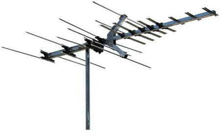
winegarddirect - Winegard 7694P
The Winegard 7694P antenna has been specifically tuned for channels 7-69. This antenna has a range for 30 miles for VHF and 25 miles for UHF signals. It is primarily an outdoor antenna and is not intended to be installed indoors.
- Active Elements: 28
- Includes hardware for mounting to a mast; antenna has a 75 ohm coax connection
- Estimated Range: 35 miles on the VHF band and 25 miles on the UHF band
- Made in America!
- Great small range directional antenna that picks up about 30 degrees wide
- *Note: This antenna can receive stations 2-6 in most areas due to the fact they are generally broadcast on higher unused UHF or VHF frequency numbers in the area. Our techs can verify this with your zip code information.
- UHF Elements: 17
- VHF Elements: 11
- Boom Length: 65"
- Width: 35"
- Element Diamter: 3/8"
- Turning Radius 43.25
- Shipping Weight 7 lbs.
|
CHANNEL |
CH 7 |
CH 9 |
CH 11 |
CH 13 |
CH 14 |
CH 32 |
CH 50 |
CH 69 |
|
dB gain over reference dipole |
8.3 | 9.6 | 8 | 9.9 | 11.5 | 10.4 | 10.7 | 9.7 |
|
Beam width at half power points |
37° | 38° | 39° | 37° | 61° | 54° | 46° | 34° |
|
Front-to-back ratio |
13dB | 16dB | 15dB | 16dB | 16dB | >20dB | 19dB | 18dB |
Other FM Antenna
Other TV Antenna
- Antennas Direct - 91XG Uni-Directional Ultra Long Range DTV Antenna
- Channel Master CM-5018 Masterpiece Antenna Series Fringe 80 Mile Antenna
- Winegard HD7084
- Solidsignal - Channel Master 4228HD 8-bay HDTV High VHF/UHF TV Antenna (4228-HD)
- Antennacraft by RadioShack MXU59
TV Antenna Forums
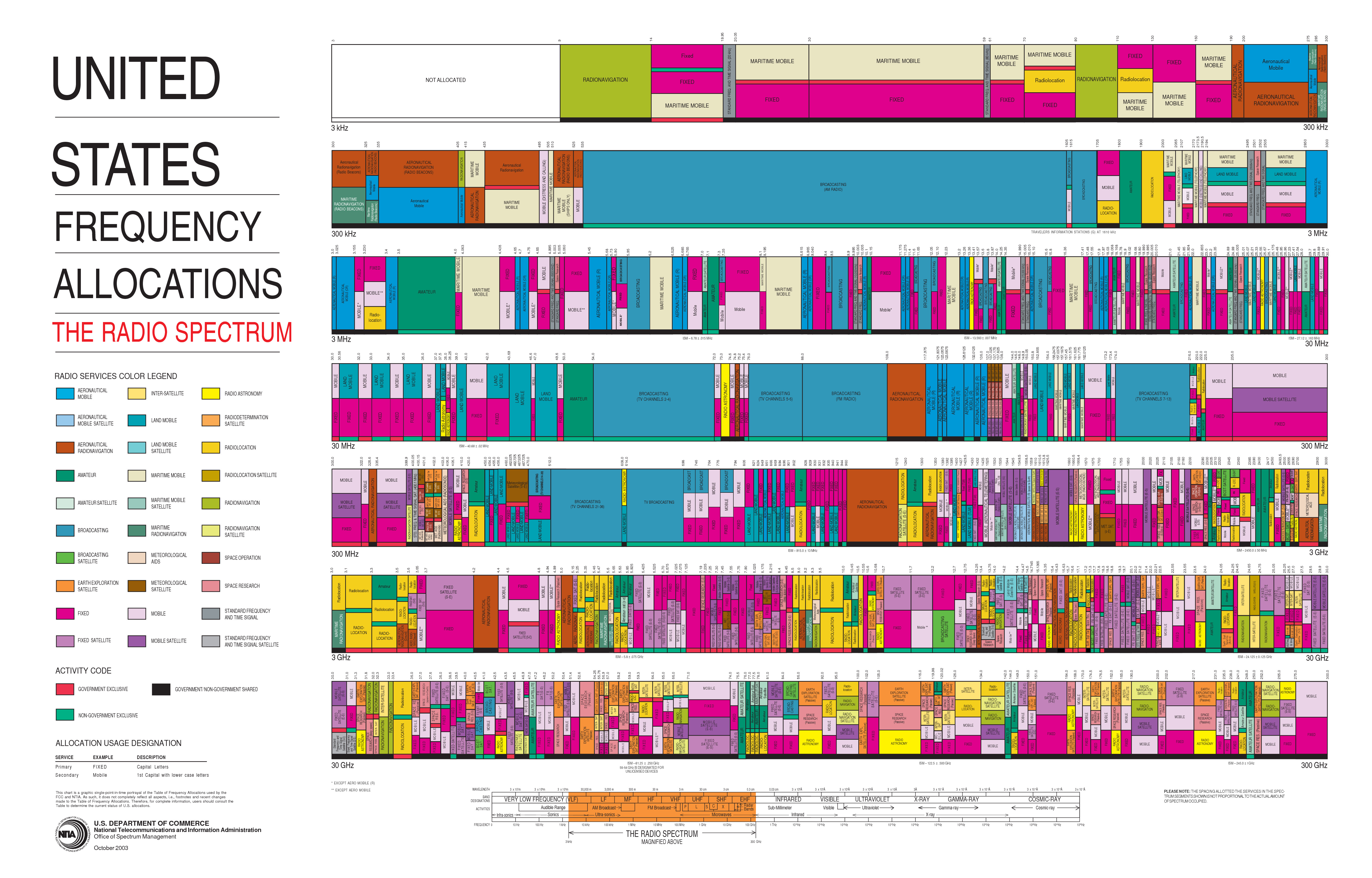
TV / Radio Spectrum
United States Frequency Allocations: The Radio Spectrum Chart (Poster)
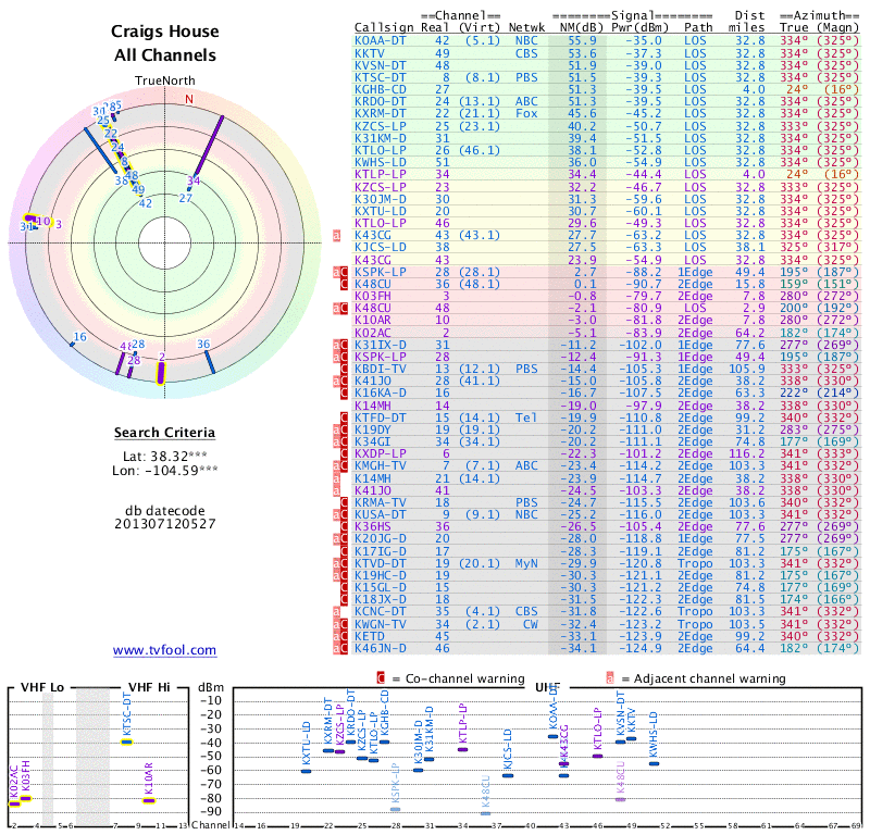
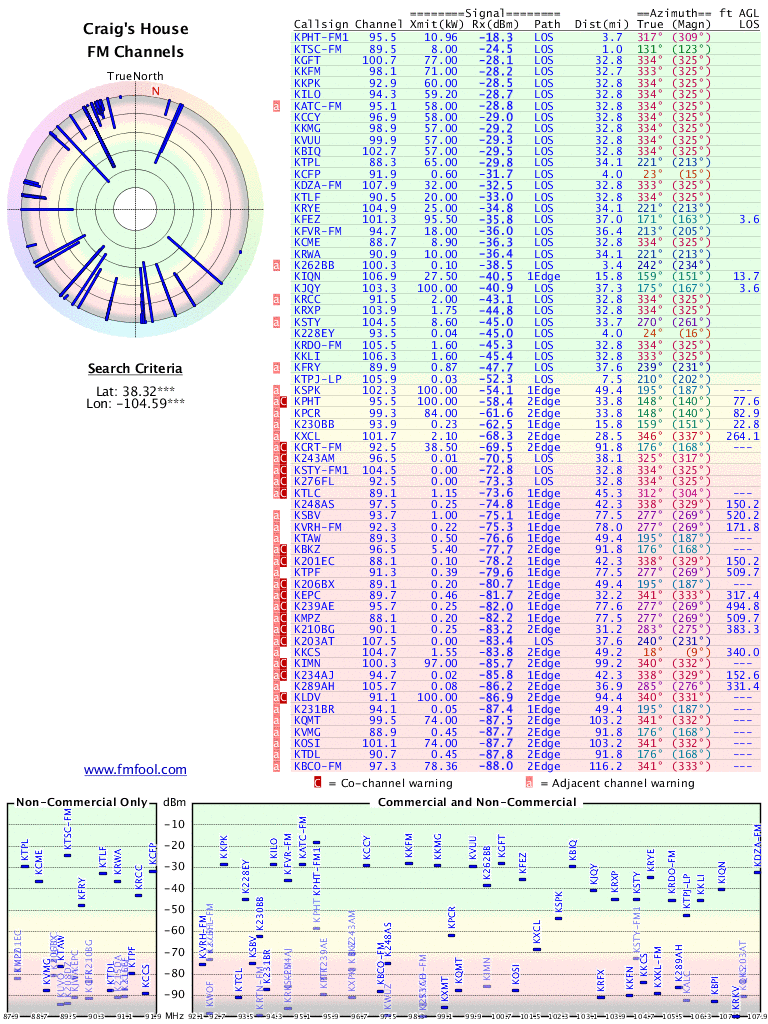
Our home coordinates are:
            38.319631, -104.591637
            +38° 19' 10.67", -104° 35' 29.89"
FM stations of interest
| Frequency | Azimuth | Call Letters | Network | Notes |
### by received power
kpht 99.5 -18.3db 3.7mi 309magn - Pueblo’s greatest hits
ktsc 89.5 -25.3db 1.0mi 123magn - CSUP Rev89
ktpl 88.3 -28.0db 34.1mi 213 magn - Power88 Moody bible network
kgft 100.7 -28.1db 32.8mi 325magn - Christian talk
kkfm 98.1 -28.2db 32.7mi 325magn - Rock
kkpk 92.9 -28.5db 32.8mi 325magn -Peak
kilo 93.2 -28.7db 32.8mi 325magn -
katc 95.1 -28.8db 32.8mi 325magn - Cat Country
kccy 96.9 -29.9db 32.8mi 325magn - New Country
kkmg 98.9 -23.2db 32.8mi 325magn - Magic top 40
kvuu 99.9 -29.3db 32.8mi 325magn - My hit music
kbiq 102.7 -29.2db 32.8mi 325magn - Christian
kcfp 91.9 -31.7db 4mi. 15magn - CPR classical
kdza 107.9 –32.6db 32.8mi 325magn - legends of class rock
ktlf 90.5 -33.0db 32.8mi 325magn - christian
krye 104.9 -34.7db 34.1mi 213magn - spanish
kfez 101.3 -35.7db 37mi 163magn - easy favorits 70’s, 80’s
kfvr 94.7 -35.9db 36.5mi 205magn - classic rock
kcme 88.7 -36.3db 32.8mi 325magn - classical
krwa 90.9 -36.4db 34.1mi 213magn - christian
kjqy 103.3 -40.8db 37.3mi 167magn - sports talk
krcc 91.5 -43.1db 32.8mi 325magn - Colorado College
krxp 103.9 -44.8db 32.8mi 325magn - alternative
ksty 104.5 -44.9db 33.7mi 261magn - Canon City country
krdo 105.5 -45.3db 32.8mi 325magn -
kkli 106.3 -45.4db 32.8mi 325magn - klite
by azimuth
kcfp 91.9 -31.7db 4mi. 15magn - CPR classical
ktsc 89.5 -25.3db 1.0mi 123magn - CSUP Rev89
kfez 101.3 -35.7db 37mi 163magn - easy favorits 70’s, 80’s
kjqy 103.3 -40.8db 37.3mi 167magn - sports talk
kfvr 94.7 -35.9db 36.5mi 205magn - classic rock
ktpl 88.3 -28.0db 34.1mi 213 magn - Power88 Moody bible network
krye 104.9 -34.7db 34.1mi 213magn - spanish
krwa 90.9 -36.4db 34.1mi 213magn - christian
ksty 104.5 -44.9db 33.7mi 261magn - Canon City country
kpht 99.5 -18.3db 3.7mi 309magn - Pueblo’s greatest hits
kgft 100.7 -28.1db 32.8mi 325magn - Christian talk
kkfm 98.1 -28.2db 32.7mi 325magn - Rock
kkpk 92.9 -28.5db 32.8mi 325magn -Peak
kilo 93.2 -28.7db 32.8mi 325magn -
katc 95.1 -28.8db 32.8mi 325magn - Cat Country
kccy 96.9 -29.9db 32.8mi 325magn - New Country
kkmg 98.9 -23.2db 32.8mi 325magn - Magic top 40
kvuu 99.9 -29.3db 32.8mi 325magn - My hit music
kbiq 102.7 -29.2db 32.8mi 325magn - Christian
kdza 107.9 –32.6db 32.8mi 325magn - legends of class rock
ktlf 90.5 -33.0db 32.8mi 325magn - christian
kcme 88.7 -36.3db 32.8mi 325magn - classical
krcc 91.5 -43.1db 32.8mi 325magn - Colorado College
krxp 103.9 -44.8db 32.8mi 325magn - alternative
krdo 105.5 -45.3db 32.8mi 325magn -
kkli 106.3 -45.4db 32.8mi 325magn - klite
TV stations of interest
| Channel | Azimuth | CallLetters | Network | Notes |
| 42 (5.1) | 334 (325) | KOAA-DT | NBC | Notes |
| 8 (8.1) | 334 (325) | KTSC-DT | PBS | Notes |
| 49 (11.1) | 334 (325) | KKTV | CBS | Notes |
| 24 (13.1) | 334 (325) | KRDO | ABC | Notes |
| 22 (21.1) | 334 (325) | KXRM | Fox | Notes |
| 23 | 333 (325) | KZCS | Azteca | Notes |
| 27 | 24 (16) | KGHB | Univision | Low power |
| 48.1 | 334 (325) | KVSN | Univision | Notes |
TV Stations at 325 magnetic
| 8 | 22 | 23 | 24 | 42 | 48 | 49 |
TVFool
FMFool
TV frequencies 14 - 83
            CH #   FREQUENCY        CH #   FREQUENCY        CH #   FREQUENCY

             14   470-476 MHz        38   614-620 MHz        62    758-764 MHz

             15   476-482 MHz        39   620-626 MHz        63    764-770 MHz

             16   482-488 MHz        40   626-632 MHz        64    770-776 MHz

             17   488-494 MHz        41   632-638 MHz        65    776-782 MHz

             18   494-500 MHz        42   638-644 MHz        66    782-788 MHz

             19   500-506 MHz        43   644-650 MHz        67    788-794 MHz

             20   506-512 MHz        44   650-656 MHz        68    794-800 MHz

             21   512-518 MHz        45   656-662 MHz        69    800-806 MHz

             22   518-524 MHz        46   662-668 MHz        70    806-812 MHz

             23   524-530 MHz        47   668-674 MHz        71    812-818 MHz

             24   530-536 MHz        48   674-680 MHz        72    818-824 MHz

             25   536-542 MHz        49   680-686 MHz        73    824-830 MHz

             26   542-548 MHz        50   686-692 MHz        74    830-836 MHz

             27   548-554 MHz        51   692-698 MHz        75    836-842 MHz

             28   554-560 MHz        52   698-704 MHz        76    842-848 MHz

             29   560-566 MHz        53   704-710 MHz        77    848-854 MHz

             30   566-572 MHz        54   710-716 MHz        78    854-860 MHz

             31   572-578 MHz        55   716-722 MHz        79    860-866 MHz

             32   578-584 MHz        56   722-728 MHz        80    866-872 MHz

             33   584-590 MHz        57   728-734 MHz        81    872-878 MHz

             34   590-596 MHz        58   734-740 MHz        82    878-884 MHz

             35   596-602 MHz        59   740-746 MHz        83    884-890 MHz

             36   602-608 MHz        60   746-752 MHz

             37   608-614 MHz        61   752-758 MHz
The North American broadcast television frequencies are on designated television channels numbered 2 through 69, approximately between 54 and 806 MHz.
| Channel | Lower edge | Video carrier | ATSC pilot | Audio carrier | Upper edge |
|---|---|---|---|---|---|
| 2 | 54 | 55.25 | 54.31 | 59.75 | 60 |
| 3 | 60 | 61.25 | 60.31 | 65.75 | 66 |
| 4 | 66 | 67.25 | 66.31 | 71.75 | 72 |
| 5 | 76 | 77.25 | 76.31 | 81.75 | 82 |
| 6 | 82 | 83.25 | 82.31 | 87.75 | 88 |
| Channel | Lower edge | Video carrier | ATSC pilot | Audio carrier | Upper edge |
|---|---|---|---|---|---|
| 7 | 174 | 175.25 | 174.31 | 179.75 | 180 |
| 8 | 180 | 181.25 | 180.31 | 185.75 | 186 |
| 9 | 186 | 187.25 | 186.31 | 191.75 | 192 |
| 10 | 192 | 193.25 | 192.31 | 197.75 | 198 |
| 11 | 198 | 199.25 | 198.31 | 203.75 | 204 |
| 12 | 204 | 205.25 | 204.31 | 209.75 | 210 |
| 13 | 210 | 211.25 | 210.31 | 215.75 | 216 |
| Channel | Lower edge | Video carrier | ATSC pilot | Audio carrier | Upper edge |
|---|---|---|---|---|---|
| 14 | 470 | 471.25 | 470.31 | 475.75 | 476 |
| 15 | 476 | 477.25 | 476.31 | 481.75 | 482 |
| 16 | 482 | 483.25 | 482.31 | 487.75 | 488 |
| 17 | 488 | 489.25 | 488.31 | 493.75 | 494 |
| 18 | 494 | 495.25 | 494.31 | 499.75 | 500 |
| 19 | 500 | 501.25 | 500.31 | 505.75 | 506 |
| 20 | 506 | 507.25 | 506.31 | 511.75 | 512 |
| 21 | 512 | 513.25 | 512.31 | 517.75 | 518 |
| 22 | 518 | 519.25 | 518.31 | 523.75 | 524 |
| 23 | 524 | 525.25 | 524.31 | 529.75 | 530 |
| 24 | 530 | 531.25 | 530.31 | 535.75 | 536 |
| 25 | 536 | 537.25 | 536.31 | 541.75 | 542 |
| 26 | 542 | 543.25 | 542.31 | 547.75 | 548 |
| 27 | 548 | 549.25 | 548.31 | 553.75 | 554 |
| 28 | 554 | 555.25 | 554.31 | 559.75 | 560 |
| 29 | 560 | 561.25 | 560.31 | 565.75 | 566 |
| 30 | 566 | 567.25 | 566.31 | 571.75 | 572 |
| 31 | 572 | 573.25 | 572.31 | 577.75 | 578 |
| 32 | 578 | 579.25 | 578.31 | 583.75 | 584 |
| 33 | 584 | 585.25 | 584.31 | 589.75 | 590 |
| 34 | 590 | 591.25 | 590.31 | 595.75 | 596 |
| 35 | 596 | 597.25 | 596.31 | 601.75 | 602 |
| 36 | 602 | 603.25 | 602.31 | 607.75 | 608 |
| 37 | 608 | 609.25 | - | 613.75 | 614 |
| 38 | 614 | 615.25 | 614.31 | 619.75 | 620 |
| 39 | 620 | 621.25 | 620.31 | 625.75 | 626 |
| 40 | 626 | 627.25 | 626.31 | 631.75 | 632 |
| 41 | 632 | 633.25 | 632.31 | 637.75 | 638 |
| 42 | 638 | 639.25 | 638.31 | 643.75 | 644 |
| 43 | 644 | 645.25 | 644.31 | 649.75 | 650 |
| 44 | 650 | 651.25 | 650.31 | 655.75 | 656 |
| 45 | 656 | 657.25 | 656.31 | 661.75 | 662 |
| 46 | 662 | 663.25 | 662.31 | 667.75 | 668 |
| 47 | 668 | 669.25 | 668.31 | 673.75 | 674 |
| 48 | 674 | 675.25 | 674.31 | 679.75 | 680 |
| 49 | 680 | 681.25 | 680.31 | 685.75 | 686 |
| 50 | 686 | 687.25 | 686.31 | 691.75 | 692 |
| 51 | 692 | 693.25 | 692.31 | 697.75 | 698[3][4] |
| Channel | Lower edge | Video carrier | ATSC carrier | Audio carrier | Upper edge |
| 52 | 698 | 699.25 | 698.31 | 703.75 | 704 |
| 53 | 704 | 705.25 | 704.31 | 709.75 | 710 |
| 54 | 710 | 711.25 | 710.31 | 715.75 | 716 |
| 55 | 716 | 717.25 | 716.31 | 721.75 | 722 |
| 56 | 722 | 723.25 | 722.31 | 727.75 | 728 |
| 57 | 728 | 729.25 | 728.31 | 733.75 | 734 |
| 58 | 734 | 735.25 | 734.31 | 739.75 | 740 |
| 59 | 740 | 741.25 | 740.31 | 745.75 | 746 |
| 60 | 746 | 747.25 | 746.31 | 751.75 | 752 |
| 61 | 752 | 753.25 | 752.31 | 757.75 | 758 |
| 62 | 758 | 759.25 | 758.31 | 763.75 | 764 |
| 63 | 764 | 765.25 | 764.31 | 769.75 | 770 |
| 64 | 770 | 771.25 | 770.31 | 775.75 | 776 |
| 65 | 776 | 777.25 | 776.31 | 781.75 | 782 |
| 66 | 782 | 783.25 | 782.31 | 787.75 | 788 |
| 67 | 788 | 789.25 | 788.31 | 793.75 | 794 |
| 68 | 794 | 795.25 | 794.31 | 799.75 | 800 |
| 69 | 800 | 801.25 | 800.31 | 805.75 | 806 |
| Channel | Lower edge | Video carrier | ATSC carrier | Audio carrier | Upper edge |
| 70 | 806 | 807.25 | - | 811.75 | 812 |
| 71 | 812 | 813.25 | - | 817.75 | 818 |
| 72 | 818 | 819.25 | - | 823.75 | 824 |
| 73 | 824 | 825.25 | - | 829.75 | 830 |
| 74 | 830 | 831.25 | - | 835.75 | 836 |
| 75 | 836 | 837.25 | - | 841.75 | 842 |
| 76 | 842 | 843.25 | - | 847.75 | 848 |
| 77 | 848 | 849.25 | - | 853.75 | 854 |
| 78 | 854 | 855.25 | - | 859.75 | 860 |
| 79 | 860 | 861.25 | - | 865.75 | 866 |
| 80 | 866 | 867.25 | - | 871.75 | 872 |
| 81 | 872 | 873.25 | - | 877.75 | 878 |
| 82 | 878 | 879.25 | - | 883.75 | 884 |
| 83 | 884 | 885.25 | - | 889.75 | 890 |
21 November 2013 » Tuned Loop AM Antenna
Parts
- amateurradiosupplies Copper Antenna Wire - 100 Feet - $26
- amateurradiosupplies Budwig End Insulator
- amateurradiosupplies Dogbone Insulator
- amateurradiosupplies No. 18 AWG CopperWeld Antenna Wire - 50 FT
- Wireman - 501 - 18 AWG solid copper-clad steel
- Wireman - 890 PULLEY, 3/4” - marine type, swivel - for 3/32” - 3/16” rope
- Wireman - 810 Budwig brand end insulators, HQ-2. Fiberglass-reinforced ABS plastic
- Wireman - 813 End insulator (pair), 3” mineral filled acrylic
- Parts Express - magnet wire
Modify that AM antenna by Bruce Carter
Modify that AM antenna by Bruce Carter
Nice article, with # loops vs. area table.
Tune your antenna for better DX - Construction of random length wire AM antenna
Tune your antenna for better DX
by Roy A. Walton (adapted by Bruce Carter)
If you use a “Pi-Section Coupler”, your antenna can be as short as 30 feet or as long as 100 feet. The combination can be made to work efficiently at all frequencies between 500 and 6800 kHz.
A MAGNETIC LOOP ANTENNA FOR SHORTWAVE LISTENING (SWL)
A MAGNETIC LOOP ANTENNA FOR SHORTWAVE LISTENING (SWL)
The PVC Loop Overall Article
Article
How to build a tuned loop antenna
http://www.iw5edi.com/ham-radio/?how-to-build-a-tuned-loop-antenna,118
Chris Ridley - BUILD A TUNED LOOP
How can you vastly improve your Medium Wave reception? its quite simple really, all you need is 120 foot of wire, a few lengths of timber and an old tuning capacitor with which you can build the answer to every DX’ers prayers, a tuned loop antenna.
MTM Scientific, Inc… AM Radio Loop Antenna
Our AM RADIO DX LOOP ANTENNA converts your portable transistor radio into a long distance receiver
Pickup Loop for AM Loop Antenna
The coupling from the antenna to the radio is through the ferrite loop antenna inside most portable AM radios. We have received several inquries about the possibility of conneting the antenna to a regular component receiver. Although every situation is different, it is generally easy to do.
Review - MTM Scientific AM Loop Antenna
The MTM Scientific AM Loop Antenna is quite a different animal from all of those however for a few reasons. First it is a large square wood frame loop measuring slightly over 17” per side which makes it at least twice the size of the other passive AM loops I mentioned. This seemed like an exciting prospect as it seemed likely it would be able to capture more signal than the smaller loops.
Loop Antennas
A loop antenna is a small multi turn loop of less than 1/10th wavelength in length. The loop is wound on a form, which may be either box (solenoid), or spiral (pancake) wound. The core material can either be air, or a powdered iron compound (Ferrite). The gain of a loop is much less than a longwire, but it has much less noise pickup. A properly designed Loop primarily responds to the magnetic component of the radio wave. Note that noise resides primarily in the electrical component. A vertical antenna responds mainly to the electrical component.
Photos of PVC Loop antennas
A loop antenna is an antenna primarily for the AM broadcast and the Longwave bands.
Loading Inductors
The Radio Board - Loop antenna questions
exray
I think the generalization about ‘how many feet’ is more of a ballpark consideration. If you’re using a typical BCB range tuning cap like 365-400pf you’re going to fall into the 50-75 ft range almost inherently for most practical sizes and thats never been a bad thing.
Now if you want to use something like 200 feet of wire (a la some of these wacky broomstick or liter-coke bottle ideas) and find a cap to tune it with you’ll immediately see the uh-oh at 1700 kcs. And the other extreme…20 feet of wire at 550kc.
That said, you’ll run into the unavailability of standard parts and having to multi-bandswitch the thing to cover BCB probably before you will encounter the differences in actual peformance.
If you are building a 2-3’ size loop with a typical BCB cap you can tune the entire range without tapping it. The difference in wire length should not be noticeable.
Medium Wave One Tube Loop Radio
I am proud to introduce you to my first loop tube radio. I had this in mind for a while and it took me a long time to get started. The radio design was simple, but how was I to make this into another show piece radio? Do I make it into a 1920’s look, or a rock n’ roll 50’s radio? This one is both. The design, and parts are something that you might have seen in a 1950’s Poptronics magazine. Then there are some hints that have that definite roaring 20’s look. The loop itself is an example as well as the art deco Garolite® front panel. The wood base gives this radio a breadboard look. I sure did it all. This puppy kept me up nights thinking how I was going to build her. I like that curve that decorates the front panel. I used a large pizza pan as a guide.
The radio is a simple regenerative type using a 6418 subminiature tube. This is a pentode tube that has a 30 volt plate maximum rating. The filament runs on 1.25 volts at 10ma. With 18 volts on the plate and a low current filament, the batteries will last a long time.
16 November 2013 » Random Length AM Antenna
Freq. / Wavelength
            λ1 = 3*10^8 m/s/1.6*10^6 Hz = 187.5 m shortest wl
            λ2 = 3*10^8 m/s/5.5*10^5 Hz = 545.5 m longest wl
| Frequency | Wavelength Meters | Wavelength Feet |
| 550k | 545m | 1788ft |
| 1600k | 187m | 614ft |
Links
Info
Parts
- amateurradiosupplies Copper Antenna Wire - 100 Feet - $26
- amateurradiosupplies Budwig End Insulator
- amateurradiosupplies Dogbone Insulator
- amateurradiosupplies No. 18 AWG CopperWeld Antenna Wire - 50 FT
- Wireman - 501 - 18 AWG solid copper-clad steel
- Wireman - 890 PULLEY, 3/4” - marine type, swivel - for 3/32” - 3/16” rope
- Wireman - 810 Budwig brand end insulators, HQ-2. Fiberglass-reinforced ABS plastic
- Wireman - 813 End insulator (pair), 3” mineral filled acrylic
- Parts Express - magnet wire
Collected Posts
Instructions for Putting up a Long-Wire Antenna
Instructions for Putting up a Long-Wire Antenna
Can you hang a random length wire outside? - Timbo in Oz
Posted by Timbo in Oz (A) on November 15, 2007 at 14:21:35
In Reply to: Antennae loop posted by sown gi on November 15, 2007 at 13:12:51:
use one side of some twisted 300 ohm ribbon as the down lead into the house and to the tuner, connect that side to the AM post and t’other to the gnd post.
then report back. the 1500 IIRC has a decent AM stage.
And one other thing, IF it did originally came with a very small loop, then you may NEED one connected to make the longish random work! OFTEN stated in the manual and true IME
most audio repair shope should have a few Small AM loops lying about.
You realy do still need an aerial as well, this is just a good ground
You realy do still need an aerial as well, this is just a good ground
Posted by Timbo in Oz (A) on November 16, 2012 at 13:57:34
In Reply to: That IS interesting, thanks! posted by 1973shovel on November 10, 2012 at 06:54:24:
A random wire (with a good ground) tuned - by a cap and a tapped coil - to each station - or broadly tuned to cover the ones you want (like mine is) will be a good deal better than just a good ground.
MUCH quieter as the AM stage’s own AGC will cope with the higher input.
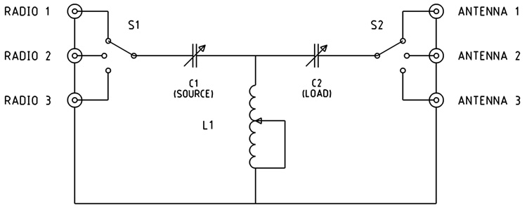
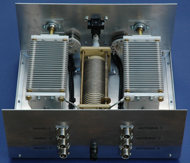
A multi-use Antenna Tuner
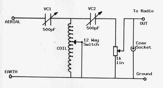
Antenna Tuning Unit
MDS975 - ATUs - ANTENNA TUNING UNITS
Below is the circuit diagram for my preferred choice of a T type circuit which includes a variable attenuator and which could not be simpler to construct. This circuit, with the coil described, covers from 500kHz medium wave to 30MHz short wave. Tuning capacitor VC1 is adjusted to match the aerial side while tuning capacitor VC2 is adjusted to match the receiver side. This circuit is often referred to as a TRANSMATCH, particularly in the USA.
My rooftop AM antenna - youtube
My rooftop AM antenna - youtube
Midnight Science Catalog - Capacitor, 365 air variable
Capacitor, 365 air variable
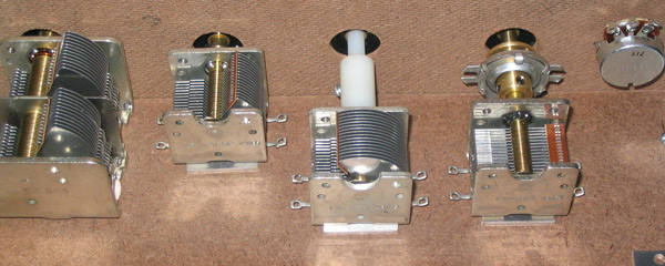
As the surplus for 365pf caps has dried up, these little beauties were getting harder and harder to find. Not anymore! The Society now has a plentiful supply; we have them manufactured. They are brand new caps, 31 blade, .010-air-gap, 1/4” tuning shaft, and CW rotation decreases capacitance. Testing indicates a capacity range of 390 (fully meshed) to 16 pf (fully open). Shaft accommodates the point knob shown (sold separately), and a reduction drive for slower tuning (also sold separately).
![]()
AM BAND ANTENNA TUNER KIT
This AM Band Tuner will work with most any crystal radio set. Tuners are attached to the antenna and inductively couple the signal captured into your crystal radio set. By adding the tuner to your station, selectivity and volume can generally be improved.
The backside of the tuner is shown at right. A dual-gang 365 pf capacitor is used to resonate the tuner coil and the antenna system as a whole. The result is an increase in the signal gleaned from the antenna and coupled to the set magnetically. The tuner uses a 6 by 5 inch front panel and a 6 by 8 in chassis. Two switches are used to configure the tuner. In addition, a nylon shaft is added to the tuning capacitor to reduce “hand capacity” while tuning. Kit time is less than one hour experienced builder and should add performance to your crystal radio station.
Variable Capacitors & Reduction Drives: Using, Mounting & Wiring.
Variable Capacitor Use Article
T-MATCH ATU
The T-Network Antenna Matching Unit
Homebrew Antenna Tuner - Steve Yates - AA5TB
Tags
- linux
- debian
- diy
- arduino
- cellphone
- turntable
- antenna
- diy_audio
- led
- rune_audio
- tuner
- chipamp
- raspberry_pi
- bluehost
- am
- mpd
- developers_to_watch
- beaglebone
- stereo_system
- headphone_amp
- i3wm
- fm
- arch_linux
- bluetooth
- nas
- preamp
- git
- javascript
- sql
- ti_cc_3000
- wifi
- reactor_safety
- volumio
- raspbian
- pptp
- Debian
- keyboard
- portable
- lp_storage
- firefox_phone
- firefox_os
- repair
- radio
- moteino_home_automation
- xmonad
- gitlab
- rails
- rails-api
- windows_os
- vm_host
- virtualbox
- electronics
- cubox
- rhombic_antenna
- diy_li_ion_battery_pack
- survival
- music_player
- headphones
- robotics
- welcome
- speaker
- subwoofer
- tear_drop_trailers
- philips_cd935
- diy_cabling
- laptop
- pickup
- hurricane_lantern
- coding
- cd_player
- bluez
- programming
- headset
- hardware_hackers
- arduino_ide
- tube_audio
- porch_steps_led
- ebay
- fm_transmitter
- coax_power_plug
- recipe
- vpn
- arduino_radio
- tv
- gammu
- stereo_receiver
- seamonkey
- thunderbird
- vinyl_lp
- cleaning
- hardware
- rs232
- max232
- gogs
- job_hunt
- phusion_passenger
- tuned_loop
- firefox
- icemonkey
- job_skills
- webmail
- spam_assassin
- irc
- security
- pc_audio
- green_chile
- moosefet
- usb
- ajax