Tag: arduino
13 March 2014 » Run socat for Arduino IO
Run socat for Arduino IO
A key element of using a Raspberry Pi for a moteino gateway is how to talk to /dev/ttyUSBX for the serial communication.
Problems
- /dev/ttyUSBX is only available if the USB/Serial connection is there.
- Need to guarantee that socat is running if /dev/ttyUSBX is available.
Survey of approaches.
- Run socat from inittab.
- Start socat at boot with /etc/rc.d
- Start socat at boot with supervisor.d
- Run socat from the JRuby gateway script.
Run socat from the JRuby gateway script.
Fork/exec management from JRuby seems to be best done with spoon
What do the JRuby experts say?
fork and exec on the JVM? JRuby to the Rescue!
JavaWorld - fork and exec on the JVM? JRuby to the Rescue!
- By Charles Nutter
-
JavaWorld May 13, 2009 11:01 PM
As you should know by now, JRuby ships with FFI, a library that allows you to bind any arbitrary C function in Ruby code. So getting fork+exec to work was a simple matter of writing a little Ruby code:
            require 'ffi'

            module Exec
             extend FFI::Library

             attach_function :my_exec, :execl, [:string, :string, :varargs], :int
             attach_function :fork, [], :int
            end

            vim1 = '/usr/bin/vim'
            vim2 = 'vim'
            if Exec.fork == 0
             Exec.my_exec vim1, vim2, :pointer, nil
            end

            Process.waitall
Update: The biggest problem with using fork+exec in this way is that you can’t guarantee nothing happens between the fork call and the exec call. If, for example, the JVM decides to GC or move memory around, you can have a fatal crash at the JVM process level. Because of that, I don’t recommend using fork + exec via FFI in JRuby, even though it’s pretty cool.
However, since this post I’ve learned of the “posix_spawn” function available on most Unix variants. It’s basically fork + exec in a single function, plus most of the typical security and IO tweaks you might do after forking and before execing. It’s definitely my recommended alternative to fork+exec for JRuby, and to make that easier I’ve bundled it up as the “spoon” gem (gem install spoon) which provides spawn and spawnp to JRuby users directly. Here’s an example session using Spoon to launch JRuby as a daemon. If you just need fork+exec on the JVM, posix_spawn or the Spoon gem are the best way to do it.
headius / daemonize.rb
             require 'rubygems'
             require 'spoon'

             Spoon.spawnp 'jruby', *ARGV
            ~/projects/jruby ➔ jruby daemonize.rb -e "puts 'starting'; while true; sleep 1; puts 'still going'; end"

            ~/projects/jruby ➔ starting
            still going
            still going
            still going
            still going


            ~/projects/jruby ➔ still going
            still going
            still going
            ps
              PID TTY           TIME CMD
              342 ttys000    0:00.06 -bash
              421 ttys000    0:00.49 /usr/bin/java -d32 -client -Djruby.memory.max=500m -Djruby.stack.max=1024k
              363 ttys001    0:00.02 -bash
            still going
            ~/projects/jruby ➔
            kistill going
            llstill going
            still going
             421still going


            ~/projects/jruby ➔
github gem - headius / spoon
A fork/exec replacement for FFI-capable implementations
Spoon is an FFI binding of the posix_spawn function (and Windows equivalent), providing fork+exec functionality in a single shot.
            Gem::Specification.new do |s|
              s.name = "spoon"
              s.version = "0.0.4"
              s.authors = ["Charles Oliver Nutter"]
              s.date = "2013-03-29"
              s.description = s.summary = "Spoon is an FFI binding of the posix_spawn function (and Windows equivalent), providing fork+exec functionality in a single shot."
              s.files = `git ls-files`.lines.map(&:chomp)
              s.require_paths = ["lib"]
              s.add_dependency('ffi')
              s.license = "Apache-2.0"
            end
/usr/bin/socat http://linux.die.net/man/3/posix_spawn http://ruby-doc.org/core-1.9.3/Signal.html
include
def self.posix_spawn(path, file_actions, spawn_attr, argv, env = ENV) int posix_spawn( pid_t *restrict pid, const char *restrict path, const posix_spawn_file_actions_t *file_actions, const posix_spawnattr_t *restrict attrp, char *const argv[restrict], char *const envp[restrict]);
int posix_spawnp( pid_t *restrict pid, const char *restrict file, const posix_spawn_file_actions_t *file_actions, const posix_spawnattr_t *restrict attrp, char *const argv[restrict], char * const envp[restrict]);
http://ruby-doc.org/core-1.9.3/Process.html#method-c-waitpid2
https://github.com/headius/spoon/blob/master/examples/ls.rb
require ‘spoon’
# # Do a recursive ls on the current directory, redirecting output to /tmp/ls.out #
file_actions = Spoon::FileActions.new file_actions.close(1) file_actions.open(1, “/tmp/ls.out”, File::WRONLY | File::TRUNC | File::CREAT, 0600) spawn_attr = Spoon::SpawnAttributes.new pid = Spoon.posix_spawn(‘/usr/bin/env’, file_actions, spawn_attr, %w(env ls -R))
Process.waitpid(pid)
https://github.com/ffi/ffi/issues/336 «««««««««««< wrong, should be issue on JRuby Fail on Raspberry Pi ARM linux JRuby. FFI not available
https://github.com/jruby/jruby/issues/1561 Fail on Raspberry Pi ARM linux JRuby. FFI not available
19 February 2014 » Raspberry Pi Radio Gateway Build
Overview
A Raspberry Pi based gateway to distributed Moteino radio connected Arduinos.
- Moteino USB attached as radio interface
- Raspberry Pi hosted gateway based on a JRuby/JVM/Reel based HTTP server
Looking for a minimal server install
Raspbian Wheezy armhf Raspberry Pi minimal image
After the Debian Wheezy armel image I made a new one based on Raspbian armhf. This one is compiled with hard float support, so basically floating point operations are MUCH faster because they are done in hardware instead of software emulation :)
Features include:
- A minimal Raspbian Wheezy installation (similar to a netinstall)
- Hard Float binaries: floating point operations are done in hardware instead of software emulation, that means higher performances
- Disabled incremental updates, means apt-get update is much faster
- Workaround for a kernel bug which hangs the Raspberry Pi under heavy network/disk loads
- 3.6.11+ hardfp kernel with latest raspberry pi patches
- Latest version of the firmwares
- Fits 1GB SD cards
- A very tiny 118MB image: even with a 2GB SD there is a lot of free space
- ssh starts by default
- The clock is automatically updated using ntp
- IPv6 support
- Just 14MB of ram usage after the boot
Other Linux images passed over
- Moebius v1.1.1 available
- Raspbian Server Edition Version 2.3
- raspbian-ua-netinst - Raspbian unattended netinstaller
The most interesting on here is the raspbian-ua-netinst. There is Github repo for it:
Github repo with raspbian-ua-netinst
I had previously used the Raspbian net installer here: RaspbianInstaller
But the notes now say: Currently we reccomend using hifi’s raspbian-ua-netinst instead if you want to use an installer rather than a pre-installed image.
Dark Basic install notes
Dark Basic Raspbian SDHC Boot image
Start with the Dark Basic install notes
You will have to extract the image with p7zip:
7za x raspbian_wheezy_20130923.img.7z
Then flash it to your SD with dd:
$ sudo dd bs=1M if=raspbian_wheezy_20130923.img of=/dev/sdc
Finally, if you have an sd larger than 1GB, grow the partition with gparted (first move the swap partition at the end).
$ sudo gparted /dev/sdc
At this point install the SDHC card on the RPI, plug in the ethernet cable, plug in the USB terminal cable which will power up the RPI.
Now use screen to watch the boot up messages.
Able to use screen to connect on laptop:
$ sudo screen /dev/ttyUSB0 115200
When connected check the stty values.
$ stty -a
Attempts to use socat instead of screen
             $ sudo socat - /dev/ttyUSB0,b115200
             $ sudo socat - /dev/ttyUSB0,b115200,raw # no
             $ sudo socat - /dev/ttyUSB0,b115200,cs7 # no
             $ sudo socat - /dev/ttyUSB0,b115200,parenb,cs7 # no
             $ sudo socat - /dev/ttyUSB0,b115200,parenb,cs8 # no
             $ sudo socat - /dev/ttyUSB0,b115200,raw,cs7 # no
             $ sudo socat - /dev/ttyusb0,b115200,raw,cs8,start=1,stop=1 # no
             $ sudo socat - /dev/ttyusb0,b115200,parenb=false,raw,cs8,start=1,stop=1 # no
             $ sudo socat - /dev/ttyUSB0,b115200,raw,cs8 # no
             $ sudo socat - /dev/ttyUSB0,b115200,raw,cs7 # no
             $ sudo socat - /dev/ttyUSB0,b115200,raw,cs8 # no
             $ sudo socat - /dev/ttyUSB0,b115200,cs8,parenb=0 # close, but not exact
             $ sudo socat - /dev/ttyUSB0,b115200,cs8,parenb=0,stop=0 # close
             $ sudo socat - /dev/ttyUSB0,cs8,parenb=0,stop=0,ixon=1,ixoff=1 # close
             $ sudo socat - /dev/ttyUSB0,cs8,parenb=0,stop=0,ixon=1,ixoff=1,echo=0

             $ sudo screen /dev/ttyUSB0 115200
             $ sudo socat /dev/ttyUSB0,raw,echo=0,crlf

             $ socat -d -d -d -d -x TCP:localhost:7758 FILE:/dev/ttyUSB0,b9600,raw
Found the IP address on the router: 192.168.88.223
ssh into the RPI and have a go. The root password is raspberry.
$ ssh root@192.168.88.223
Change the root password
passwd
You will have to reconfigure your timezone after the first boot:
# dpkg-reconfigure tzdata
The keyboard layout:
# dpkg-reconfigure console-data
And the localization:
# dpkg-reconfigure locales
Some docs
And proceed
Change the hostname
Edit /etc/hostname to have the hostname.
            $ cat /etc/hostname
            pika
Edit /etc/hosts and a line with the new hostname.
            $ cat /etc/hosts
            127.0.0.1	localhost
            127.0.0.1	pika       <<< added this line with hostname
             ...
Add a user
            # adduser craig

            Note that from now on:
            # prompt means run as root.
            $ prompt means run as user craig
# su - craig
Generate a key pair for the new user
$ ssh-keygen
Check the Debian version
            $ cat /etc/debian_version
            7.2
Update the system
            # apt-get update
            # apt-get dist-upgrade
Install python, vim, tmux, git
# apt-get install python
# apt-get install vim tmux git
Personalize git
            # git config --global user.name "Your Name Here"
            Sets the default name for git to use when you commit

            # git config --global user.email "your_email@example.com"
            Sets the default email for git to use when you commit
Set up the vim dotfiles and vundle.
            $ git clone git@github.com:CootCraig/dotfiles_again.git

            $ cd dotfiles_again/linux
            $ bash ./install.sh

            cd ~/dotfiles_again/windows/vimfiles/bundle
            git clone https://github.com/gmarik/vundle.git
There are some notes on using vundle in the file ~/.vim/bundle/Readme.txt The Raspbian vim does not have python support, so disable UltiSnips vim script. Comment out the following line in ~/.vimrc
            Bundle 'vim-scripts/UltiSnips'
              to
            "Bundle 'vim-scripts/UltiSnips'
And then run BundleInstall.
in vim. :BundleInstall
password less ssh
These instructions worked fine.
How to set up ssh so you aren’t asked for a password
Add the contents of the public key file into ~/.ssh/authorized_keys on the remote site (the file should be mode 600).
make user a sudoer
            # apt-get install sudo
            # adduser craig sudo
Pause and make a backup of the SDHC image
On the Ubuntu host.
            $ sudo dd bs=1M if=/dev/sdc of=pika_20140220_1441.img
            7519+0 records in
            7519+0 records out
            7884242944 bytes (7.9 GB) copied, 446.404 s, 17.7 MB/s

            $ 7za a -t7z pika_20140220_1441.img.7z pika_20140220_1441.img

            $ ls -l pika_2014*
            -rw-r--r-- 1 craig craig 7884242944 Feb 20 14:49 pika_20140220_1441.img
            -rw-r--r-- 1 craig craig  254215741 Feb 20 15:09 pika_20140220_1441.img.7z
Install Compiler tools
            # apt-get install build-essential checkinstall libtool automake uuid-dev

            The following extra packages will be installed:
              autoconf autotools-dev binutils bzip2 cpp cpp-4.6 dpkg-dev fakeroot g++ g++-4.6 gcc gcc-4.6 libalgorithm-diff-perl libalgorithm-diff-xs-perl libalgorithm-merge-perl libdpkg-perl libfile-fcntllock-perl libgmp10 libgomp1 libltdl-dev
              libltdl7 libmpc2 libmpfr4 libstdc++6-4.6-dev libtimedate-perl m4 make
            Suggested packages:
              autoconf2.13 autoconf-archive gnu-standards autoconf-doc gettext binutils-doc bzip2-doc cpp-doc gcc-4.6-locales debian-keyring gcc-4.6-doc libstdc++6-4.6-dbg gcc-multilib manpages-dev automake1.9 flex bison gdb gcc-doc
              libmudflap0-4.6-dev libgcc1-dbg libgomp1-dbg libquadmath-dbg libmudflap0-dbg binutils-gold libtool-doc libstdc++6-4.6-doc automaken gfortran fortran95-compiler gcj make-doc
            The following NEW packages will be installed:
              autoconf automake autotools-dev binutils build-essential bzip2 checkinstall cpp cpp-4.6 dpkg-dev fakeroot g++ g++-4.6 gcc gcc-4.6 libalgorithm-diff-perl libalgorithm-diff-xs-perl libalgorithm-merge-perl libdpkg-perl
              libfile-fcntllock-perl libgmp10 libgomp1 libltdl-dev libltdl7 libmpc2 libmpfr4 libstdc++6-4.6-dev libtimedate-perl libtool m4 make uuid-dev
            0 upgraded, 32 newly installed, 0 to remove and 0 not upgraded.
            Need to get 26.8 MB of archives.
            After this operation, 69.2 MB of additional disk space will be used.
Zeromq build and install
Source for stable release 3.2.4
This is supported by ffi-rzmq, the JRuby librar I plan to use. I unpacked for build at:
# cd /opt/zeromq/zeromq-3.2.4
The installation will be to /usr/local/
            # ./configure --help
            Installation directories:
              --prefix=PREFIX         install architecture-independent files in PREFIX
                                      [/usr/local]
              --exec-prefix=EPREFIX   install architecture-dependent files in EPREFIX
                                      [PREFIX]
Build and install.
            # ./configure
            # make
            # checkinstall
A debian package was left here:
/opt/zeromq/zeromq-3.2.4/zeromq_3.2.4-1_armhf.deb
Set up serial console
From /etc/inittab
            ...
            # Example how to put a getty on a serial line (for a terminal)
            #
            #T0:23:respawn:/sbin/getty -L ttyS0 9600 vt100
            #T1:23:respawn:/sbin/getty -L ttyS1 9600 vt100
            ...
However, this is the device file we see:
            $ ls -l /dev/ttyAMA0
            crw-rw---T 1 root dialout 204, 64 Dec 31  1969 /dev/ttyAMA0
So let’s add this line to /etc/inittab
            ...
            # Example how to put a getty on a serial line (for a terminal)
            #
            #T0:23:respawn:/sbin/getty -L ttyS0 9600 vt100
            T0:23:respawn:/sbin/getty -L ttyAMA0 115200 vt100
            #T1:23:respawn:/sbin/getty -L ttyS1 9600 vt100
            ...
Post to raspberrypi.org/forum about Edimax EW-7811UN
I have failed to get Wifi working and would like some help. I’m not sure how how to troubleshoot from here. Here are some details on my setup.
Using this OS image. I want a minimal install with no X.
Dark Basic Raspbian SDHC Boot image
With this USB wifi plug: Edimax EW-7811UN
Boot time messages include these related to the Edimax plug.
            [    3.232011] usb 1-1.2: new high-speed USB device number 4 using dwc_otg
            [    3.364155] usb 1-1.2: New USB device found, idVendor=7392, idProduct=7811
            [    3.380505] usb 1-1.2: New USB device strings: Mfr=1, Product=2, SerialNumber=3
            [    3.399033] usb 1-1.2: Product: 802.11n WLAN Adapter
            [    3.411807] usb 1-1.2: Manufacturer: Realtek
            [    3.417625] usb 1-1.2: SerialNumber: 00e04c000001
             ...
            [   15.826605] IPv6: ADDRCONF(NETDEV_UP): wlan0: link is not ready
System reports as.
            root@pika:~# uname -a
            Linux pika 3.6.11+ #545 PREEMPT Fri Sep 20 23:57:55 BST 2013 armv6l GNU/Linux
More evidence the Edimax Wifi is seen
            root@pika:~# lsusb
            Bus 001 Device 002: ID 0424:9512 Standard Microsystems Corp.
            Bus 001 Device 001: ID 1d6b:0002 Linux Foundation 2.0 root hub
            Bus 001 Device 003: ID 0424:ec00 Standard Microsystems Corp.
            Bus 001 Device 004: ID 7392:7811 Edimax Technology Co., Ltd EW-7811Un 802.11n Wireless Adapter [Realtek RTL8188CUS]
The wifi driver module is loaded
            root@pika:~# lsmod
            Module                  Size  Used by
             ...
            8192cu                490361  0
             ...
Output of iwconfig
            root@pika:~# iwconfig
            wlan0     unassociated  Nickname:"<WIFI@REALTEK>"
                      Mode:Auto  Frequency=2.412 GHz  Access Point: Not-Associated
                      Sensitivity:0/0
                      Retry:off   RTS thr:off   Fragment thr:off
                      Encryption key:off
                      Power Management:off
                      Link Quality:0  Signal level:0  Noise level:0
                      Rx invalid nwid:0  Rx invalid crypt:0  Rx invalid frag:0
                      Tx excessive retries:0  Invalid misc:0   Missed beacon:0
The MicroTik Router is seen.
            root@pika:~# iwlist wlan0 scan
            wlan0     Scan completed :
                      Cell 01 - Address: D4:CA:6D:56:86:59
                                ESSID:"Pirates"
                                Protocol:IEEE 802.11bgn
                                Mode:Master
                                Frequency:2.412 GHz (Channel 1)
                                Encryption key:on
                                Bit Rates:300 Mb/s
                                Extra:wpa_ie=dd160050f20101000050f20401000050f20401000050f202
                                IE: WPA Version 1
                                    Group Cipher : CCMP
                                    Pairwise Ciphers (1) : CCMP
                                    Authentication Suites (1) : PSK
                                Extra:rsn_ie=30120100000fac040100000fac040100000fac02
                                IE: IEEE 802.11i/WPA2 Version 1
                                    Group Cipher : CCMP
                                    Pairwise Ciphers (1) : CCMP
                                    Authentication Suites (1) : PSK
                                Quality=100/100  Signal level=100/100
Contents of /etc/network/interfaces.
            root@pika:/etc/network# cat /etc/network/interfaces
            # interfaces(5) file used by ifup(8) and ifdown(8)
            auto lo
            iface lo inet loopback

            allow-hotplug eth0
            iface eth0 inet dhcp

            allow-hotplug wlan0
            iface wlan0 inet dhcp
              wpa-ssid Pirates
              wpa-psk thepassword
But I have not been able to enable the Wifi.
            root@pika:~# ifup wlan0
            Internet Systems Consortium DHCP Client 4.2.2
            Copyright 2004-2011 Internet Systems Consortium.
            All rights reserved.
            For info, please visit https://www.isc.org/software/dhcp/

            [ 1389.028246] IPv6: ADDRCONF(NETDEV_UP): wlan0: link is not ready
            Listening on LPF/wlan0/80:1f:02:a2:df:94
            Sending on   LPF/wlan0/80:1f:02:a2:df:94
            Sending on   Socket/fallback
            DHCPDISCOVER on wlan0 to 255.255.255.255 port 67 interval 5
            DHCPDISCOVER on wlan0 to 255.255.255.255 port 67 interval 8
            DHCPDISCOVER on wlan0 to 255.255.255.255 port 67 interval 11
            DHCPDISCOVER on wlan0 to 255.255.255.255 port 67 interval 15
            DHCPDISCOVER on wlan0 to 255.255.255.255 port 67 interval 18
            DHCPDISCOVER on wlan0 to 255.255.255.255 port 67 interval 4
            No DHCPOFFERS received.
            No working leases in persistent database - sleeping.
Note, the MicroTik router Wifi is in use by all the laptops we have tried.
Set up wifi
- Installing the Edimax EW-7811UN wireless adapter on Raspberry Pi
- How to Setup Wi-Fi On Your Raspberry Pi via the Command Line
- savagehomeautomation - Raspberry Pi - Installing the Edimax EW-7811Un USB WiFi
- Debian - WiFi How to Use
- jeffskinnerbox - wifi-support-on-raspberry-pi
- Debian page - rtl819x
todo list
done
- password less ssh
- make user a sudoer
- checkinstall and compile tools
- zeromq compile and install
- serial console
todo
- wifi setup
- fixed IP address
- Oracle JVM
- JRuby
- JRuby/Reel test
30 March 2014 » Arduino Hardware Notes
Power Supply parts
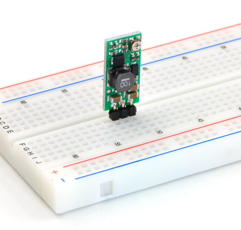
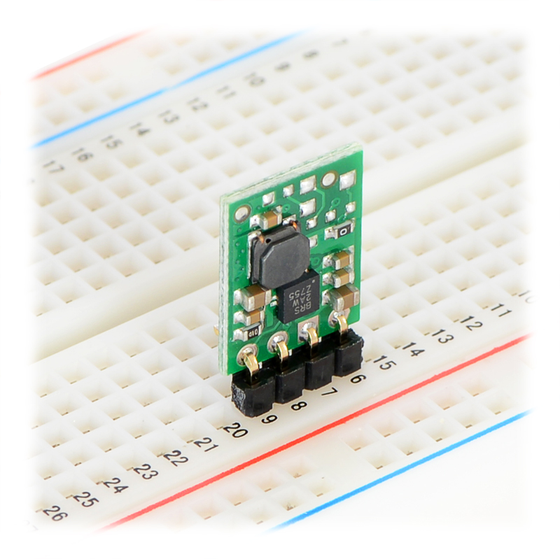
Pololu Adjustable Boost Regulator 2.5-9.5V
$11.95
Overview
The Pololu adjustable boost regulator is a very flexible switching regulator (also called a switched-mode power supply, SMPS, or DC-to-DC converter) that can generate voltages higher than its input voltage. We offer two adjustable ranges: approximately 2.5 V to 9.5 V and 4 V to 25 V. The output voltage can be set using the trimmer potentiometer in the upper-right corner of the board. The input voltage range is 1.5 V to 16 V (the input voltage should be kept below the output voltage). The integrated 2 A switch allows for output currents high enough to drive small motors, as in our 3pi robot, and allows large voltage gains, such as obtaining 24 V from two NiMH or NiCd cells.
Some example applications include:
- Powering 5 V or 3.3 V systems from lower-voltage batteries
- Powering 5 V subsystems (e.g. sensors) in lower-voltage (e.g. 3.3 V) systems
- Achieving consistent actuator operation when powered by fluctuating batteries
- Powering high-brightness LEDs or a large number of LEDs in series
Feature summary
- input voltage: 1.5 V to 16 V
- output adjustable from 2.5 V to 9.5 V or 4 V to 25 V
- 750 kHz switching frequency
- 2 A switch (and input) limit
- integrated over-temperature and over-current shutoff
- typical efficiency of 80-90% when doubling voltage and with 100-500 mA output
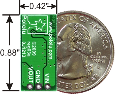
- small size: 10.7 x 22.4 x 5.8 mm (0.42″ x 0.88″ x 0.23″)
- weight without header pins: 1.6 g (0.06 oz)
Feature summary
- input voltage: 1.5 V to 16 V
- output adjustable from 2.5 V to 9.5 V or 4 V to 25 V
- 750 kHz switching frequency
- 2 A switch (and input) limit
- integrated over-temperature and over-current shutoff
- typical efficiency of 80-90% when doubling voltage and with 100-500 mA output
- small size: 10.7 x 22.4 x 5.8 mm (0.42″ x 0.88″ x 0.23″)
- weight without header pins: 1.6 g (0.06 oz)
Connections
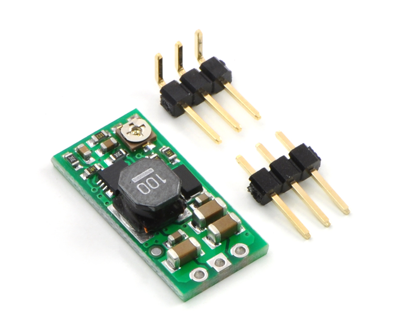
The boost regulator has just three connections: the input voltage, ground, and the output voltage. These three connections are labeled on the back side of the PCB, and they are arranged with a 0.1″ spacing along the edge of the board for compatibility with standard solderless breadboards and perfboards and connectors that use a 0.1″ grid. You can solder wires directly to the board or solder in either the 3×1 straight male header strip or the 3×1 right-angle male header strip that is included.
Setting the output voltage
The output voltage can be adjusted using a meter and a light load (e.g. a 10 kΩ resistor). Turning the potentiometer clockwise increases the output voltage. The output voltage can be affected by a screwdriver touching the potentiometer, so the output measurement should be done with nothing touching the potentiometer.
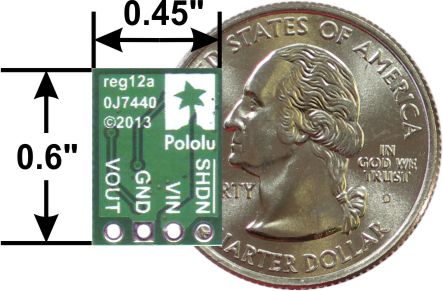
Pololu 5V Step-Up Voltage Regulator U1V11F5
$4.95
This compact (0.45″×0.6″) U1V11F5 switching step-up (or boost) voltage regulator efficiently generates 5 V from input voltages as low as 0.5 V. Unlike most boost regulators, the U1V11F5 offers a true shutdown option that turns off power to the load, and it automatically switches to a linear down-regulation mode when the input voltage exceeds the output. The pins have a 0.1″ spacing, making this board compatible with standard solderless breadboards and perfboards.
Overview
This 5 V boost (step-up) voltage regulator generates higher output voltages from input voltages as low as 0.5 V, and it also automatically switches to a linear down-regulation mode when the input voltage exceeds the output. This makes it great for powering 5 V electronics projects from 1 to 3 NiMH, NiCd, or alkaline cells or from a single lithium-ion cell. Additionally, unlike most boost regulators, this unit offers a true shutdown option that turns off power to the load (with typical boost regulators, the input voltage will pass directly through to the output when they are disabled).
When boosting, this module acts as a switching regulator (also called switched-mode power supplies (SMPS) or DC-to-DC converters) and has a typical efficiency between 70% to 90%. The available output current is a function of the input voltage, output voltage, and efficiency (see Typical Efficiency and Output Current section below), but the input current can typically be as high as 1.2 A.
Features
- Input voltage: 0.5 V to 5.5 V
- Fixed 5 V output with 4% accuracy
- True shutdown option that turns off power to the load
- Automatic linear down-regulation when the input voltage is greater than the output voltage
- 1.2 A switch allows for input currents up to 1.2 A
- Good efficiency at light load: <1 mA typical no-load quiescent current, though it can exceed 1 mA for very low input voltages (<100 μA typical quiescent current with SHDN = LOW)
- Integrated over-temperature shutoff
- Small size: 0.45″ × 0.6″; × 0.1″ (12 × 15 × 3 mm)
Connections
The boost regulator has four connections: shutdown (SHDN), input voltage (VIN), ground (GND), and output voltage (VOUT).
The SHDN can be driven low (typically under 0.4 V) to power down the regulator and turn off power to the load (unlike most boost regulators, the input power does not pass through to the output when the board is disabled). This pin is internally pulled up to VIN through an 100 kΩ resistor, so it can be left disconnected or connected directly to VIN if you do not need to use the disable feature. The disable threshold is a function of the input voltage as follows:
- For VIN < 0.8 V, SHDN voltage must be below 0.1×VIN to disable the regulator and above 0.9×VIN to enable it.
- For 0.8 V ≤ VIN ≤ 1.5 V, SHDN voltage must be below 0.2×VIN to disable the regulator and above 0.8×VIN to enable it.
- For VIN > 1.5 V, SHDN voltage must be below 0.4 V to disable the regulator and above 1.2 V to enable it.
- The input voltage, VIN, must be at least 0.5 V for the regulator to turn on. However, once the regulator is on, the input voltage can drop as low as 0.3 V and the 5 V output voltage will be maintained on VOUT. Unlike standard boost regulators, this regulator has an additional linear down-regulation mode that allows it to convert input voltages as high as 5.5 V down to 5 V for small to moderate sized loads (for example, in our tests, the adjustable version of this regulator was able to supply 300 mA while converting an input of 5.5 V down to 1.8 V). When the input voltage exceeds 5 V, the regulator automatically switches to this down-regulation mode. The input voltage should not exceed 5.5 V. Please be wary of destructive LC spikes that might cause the input voltage to surpass 5.5 V (see below for more information).
10 March 2014 » Arduino Coding Notes
Arduino Coding Notes
serialEvent()
Called when data is available. Use Serial.read() to capture this data.
Demonstrates use of the SerialEvent() function. SerialEvent() is called after a loop(), if there is serial data in the buffer.
String class
Data Structures and Algorithms
Data Structures and Algorithms
QueueArray
It is created to help adding FIFO (First In - First Out) Abstract Data Structure to a program for any use.
QueueList
Writing a Library for Arduino
alexanderbrevig - Simple templated FIFO class
alexanderbrevig - Simple templated FIFO class
Robin2 - Demonstration code for several things at the same time
forum.arduino.cc - Demonstration code for several things at the same time
Robin2 - March 04, 2014, 07:28:03 am
My sketch uses the concept in “blink without delay” to cause three LEDs to blink at different intervals, a fourth LED is controlled by a button and a servo sweeps back and forth at two different speeds. The idea is to demonstrate how different processes can be accommodated in the same general framework.
It also uses the “state machine” concept to manage the various activities and enable the different functions to determine what to do.
I have deliberately designed the sketch as a series of short functions. Short pieces of code are much easier to understand and debug and it will be an easy matter for a user to delete functions that they don’t need or to duplicate and modify functions if they need more of the same (for example to flash 5 LEDS at different intervals).
There is a case for saying there is too much in the sketch but I concluded that the larger number of activities is a better demonstration of the capabilities of this approach.
SeveralThingsAtTheSameTimeRev1.ino
arduino.cc tutorial - Blink Without Delay
Sometimes you need to do two things at once. For example you might want to blink an LED (or some other time-sensitive function) while reading a button press or other input. In this case, you can’t use delay(), or you’d stop everything else the program while the LED blinked. The program might miss the button press if it happens during the delay(). This sketch demonstrates how to blink the LED without using delay(). It keeps track of the last time the Arduino turned the LED on or off. Then, each time through loop(), it checks if a long enough interval has passed. If it has, it toggles the LED on or off.
SimpleTimer Library for Arduino
- SimpleTimer Library for Arduino
- Author: Marcello Romani
- Contact: mromani@ottotecnica.com
- License: GNU LGPL 2.1+
SimpleTimer Library for Arduino
This is (yet another) simple library to launch timed actions.
It’s based on millis(), thus it has 1 ms resolution.
It uses polling, so no guarantee can be made about the exact time when a callback is fired. For example, if you setup the library so that it calls a function every 2ms, but this function requires 5ms to complete, then you’ll have an invocation every 5ms.
For applications where non-strict timing is enough, not using interrupts avoids potential problems with global variables shared between the interrupt service routine and the main program, and doesn’t consune a hardware timer.
Nick Gammon - How to do multiple things at once … like cook bacon and eggs
Nick Gammon - How to do multiple things at once … like cook bacon and eggs
09 February 2014 » Arduino IDE
Makefile alternative to Arduino IDE
I am goint to try out the Github Makefile project for Arduino from Sudar Muthu
A Makefile for Arduino Sketches - managed by Sudar Muthu
This is a very simple Makefile which knows how to build Arduino sketches. It defines entire workflows for compiling code, flashing it to Arduino and even communicating through Serial monitor. You don’t need to change anything in the Arduino sketches.
Installation Options
Through package
If you’re using FreeBSD, Debian or Ubuntu, you can find this in the arduino-mk package and can be installed using apt-get or aptitude.
From source
Download the latest release
Or clone it from Github using the command git clone Github Repo
Sudar Muthu
Night Dreaming (by Sudar) WordPress, JavaScript, Android, Arduino and some random stuff
Hello and Welcome
I am Sudar and this is my personal site. It serves as a starting point for most of the information I have put on the web. I started this site as a hobby so that I can return back what I can to this online world from where I have learned and still learning so many things. Have a nice sta
Features
- Very robust
- Highly customizable
- Supports all official AVR-based Arduino boards
- Supports chipKIT
- Works on all three major OS (Mac, Linux, Windows)
- Auto detects serial baud rate and libraries used
- Support for *.ino and *.pde sketches as well as raw *.c and *.cpp
- Support for Arduino Software versions 1.0.x as well as 0.x. Support for Arduino 1.5.x is still work in progress
- Automatic dependency tracking. Referred libraries are automatically included in the build process. Changes in *.h files lead to recompilation of sources which include them
Article / guide - Compiling Arduino sketches using Makefile
One of the main reasons why Arduino is very popular with beginners is that it is completely self-contained which makes it very easy to use. Once you have an Arduino board, all you have to do is to download the software and within minutes you can make your first led blink. The software has everything you need right from the IDE, to the compiler and even serial monitor to communicate with Arduino, all within one single package.
While the Arduino IDE is very good for beginners, you might start to feel its limitations, once you start working with it regularly. I use vim for everything and always wished writing Arduino sketches in vim.
I configured Arduino IDE, to use an external editor and started using vim to write code and then Arduino IDE to compile and upload. While this worked for sometime, I started to feel the need for a proper makefile so that I can do everything from vim itself.
My Setup and Use Log
Get the Linux tarball.
            lug$ cd /opt/Arduino
            log$ wget http://arduino.googlecode.com/files/arduino-1.0.5-linux64.tgz
            lug$ tar xzf arduino-1.0.5-linux64.tgz
            lug$ ln -s arduino-1.0.5 arduino
            lug$ ls -l
            lrwxrwxrwx 1 craig craig       13 Mar 23 14:45 arduino -> arduino-1.0.5
            drwxr-xr-x 8 craig craig     4096 May 17  2013 arduino-1.0.5
Install dependencies
The Makefile delegates resetting the board to a short Perl program. You’ll need to install Device::SerialPort and YAML library.
On Debian or Ubuntu:
            apt-get install libdevice-serialport-perl
            apt-get install libyaml-perl
Clone Arduino-Makefile from github
I forked Arduino-Makefile from sudar.
            $ mkdir /opt/sudar; cd /opt/sudar
            $ git clone git@github.com:CootCraig/Arduino-Makefile.git
            $ cd /opt/sudar/Arduino-Makefile
Pull in upstream changes
            $ git remote add upstream https://github.com/sudar/Arduino-Makefile.git
            $ git fetch upstream
            $ git merge upstream/master
Set up git branches for craig local working changes. Leave master as copy of upsteam.
             $ git checkout -b craig
             Switched to a new branch 'craig'
             craig@lug:/opt/sudar/Arduino-Makefile$ git branch
             * craig
               master
             $ git checkout -b craig-develop
             Switched to a new branch 'craig-develop'
             $ git branch
               craig
             * craig-develop
               master
Setup environment variables
What are the avr packages.
            $ dpkg --get-selections |grep avr
            avr-libc					install
            avrdude						install
            binutils-avr					install
            gcc-avr						install
Where are the avr files.
            /usr/bin/avr-g++
            /usr/bin/avrdude
            /usr/lib/avr/lib/libc.a
            /usr/lib/avr/bin/ar
            /usr/lib/gcc/avr/4.7.2/
~/.profile
            export ARDUINO_DIR=/opt/arduino/arduino
            export ARDMK_DIR=/opt/sudar/Arduino-Makefile
            export AVR_TOOLS_DIR=/usr
Example sketch Makefile
/opt/sudar/Arduino-Makefile/Arduino.mk
Per sketch variables
After the global settings, you will need to specify the following variables for each sketch
BOARD_TAG – The Arduino board that you are using. By default Uno is used ARDUINO_PORT – The serial port where Arduino is connected ARDUINO_LIBS – Space separated set of libraries that are used by your sketch
25 January 2014 » Jeenodes
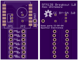
I just received from Sparkfun a few RFM12B wireless modules to experiment with. They’re great little things – you get a FIFO in, a FIFO out, all the RF stuff is taken care of, and you have super flexibility with all the network layers above that. The best part is, the relatively low complexity compared to something like a ZigBee means both that there’s no extraneous fluff when your application doesn’t need it, and the cost is just right at $7/module in low quantities. But annoyingly, they can be had in a SMD module with 2mm pin pitch – not very 100mil breadboard friendly. Not wanting to deal with that. I whipped up a basic passive breakout board to have on hand. Inevitably, this will see updates as I do things like add regulators and level shifters for particular projects. For now, it just makes breadboarding easy. To get the files, head over to the Github repository at https://github.com/alexwhittemore/RFM12B-Breakout. I’ve ordered 6 from OSHPark, I’ll report back in a couple weeks how they turned out.
This board is the perfect way to interface traditional Arduinos (or other microcontrollers) to JeeNodes. While we like our JeeLink modules a lot, as an easy way to get going with wireless, this board is a quick and easy add-on to Arduinos, to leverage your current technology. The RFM12B Board is a compact breakout board for HopeRF’s RFM12B radio module, as featured on all JeeNode and JeeLink boards. If you are looking for an affordable way to add wireless communication to your Arduino (compatible) board, this is the board to get.
25 January 2014 » Step Light Control
Now looking at Modeino instead of JeeNodes
- Tutorial on MosFET PWM LED dimming
- joost - Dimming 12v LED dimming with MosFET
- instructables - Semiconductor totem-pole
- Adafruit - N-channel power MOSFET - 30V / 60A
- JeeNodes got me looking at arduino with radio
- JeeLabs - Dive into JeeNodes
- Modern Device is US seller of JeeLabs
Radios are available in 433 MHz & 915 MHz in the US, all unlicensed ISM (Industrial, Scientific, Medical) bands.
The JeeNode Kit contains all the parts needed to build a JeeNode v6 – including an ATmega328p processor and an RFM12B radio module. The processor chip is pre-flashed with the Arduino boot loader and the RF12demo sketch, so it works to talk to another JeeNode right out of the box.
- Modern Device - Jee Proto Board $4.75
- Modern Device - JeeLabs Lux Plug
- JeeLabs - Light detector
- Modern Device - JeeLabs Relay Plug $14.00
- Meet the Relay Plug
- Modern Device - JeeLabs MOSFET Plug Kit $14.00
- Modern Device - JeeLabs Dimmer Plug $12.50
- JeeLabs - Meet the LED Node
- Modern Device - JeeLabs LED Node v2 Kit $28.00
- Modern Device - Jee Labs battery power board
- Adafruit - 6 push buttons example
- Modern Device - Jeelabs memory plug
- Adafruit Assembled Data Logging shield for Arduino - ID: 1141
Hardware newbie project - Wireless exterior LED strip control.
Here is an introduction of my first attempt at an Arduino project.
I have installed
260 inches of this 12v LED strip into my front steps.
My estimate of maximum power consumed is 32W as shown here. Their rating is 24W for a 16.4 foot reel. So my power estimate is
260 in. X (24w / 197in) ~= 32W.
The strip is too bright by itself so I use a PWM dimmer from LEDWholesalers set about as low as it will go.
What I would like to do is use a JeeNode and LEDnode pair to make a remote controller for the lights.
- Main control: On / Off / Sunset timer
- Select sunset timer duration: 2 / 4 / 6 hours
- Restart timer momentary switch if in Sunset timer mode.
- Brightness control rotary dial
I’m hoping to get some help and encouragement here and to end up with a sweet controller for our LED step lighting.
Tinker Kit MosFET
This module switches a high current load using a high power transistor. Unlike a mechanical relay, this is capable of high speed switching for use with PWM.
Output: This module lets you control devices operating at a maximun of 24VDC with an Arduino pin. To wire the module, connect the power supply for your device (max 24 V) to the V+ and GND terminals. Connect the device to M+ and M-. Be aware of your circuit’s polarity, you could damage your components if it is not wired correctly.
Module Description: This module features an IRF520 power MOSFET transistor, a kick-back diode, a standard TinkerKit 3pin connector,a signal amplifier, a green LED that signals that the module is correctly powered and one yellow LED whose brightness depends on the input signal received by the module.
SparkFun Rotary Encoder COM-09117
Description: This is a 12-step rotary encoder with a nice ‘clicking’ feel. It’s breadboard friendly, and has a pretty handy select switch (by pushing in on the knob). The encoder is different from a potentiometer in that an encoder has full rotation without limits. The unit outputs gray code so that you can tell how much and in which direction the encoder has been turned.
JeeLabs - 16-channel input multiplexer
The Input Plug is a small board containing a CD4067 16-channel analog multiplexer plus a dedicated ATtiny microcontroller to take care of channel selection. It allows you to connect up to 16 analog inputs to a single AIO pin on any port. There is an “InputPlug” class in the Ports library to interface with this board and perform the channel selection.
This board can also be used as 16-channel digital input multiplexer, and even for digital outputs or PWM – with the restriction than a channel goes into high-impedance mode when not selected (there is no latching or buffering).
Sparkfun - Momentary Push Button Switch - 12mm Square
Description: This is a standard 12mm square momentary button. What we really like is the large button head and good tactile feel (it ‘clicks’ really well). This button is great for user input on a PCB or a good, big reset button on a breadboard. Breadboard friendly!
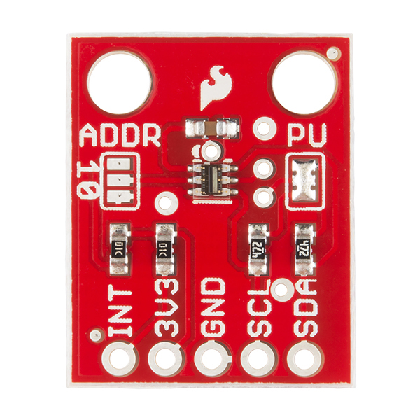
Sparkfun - TSL2561 Luminosity Sensor Breakout
The TSL2561 Luminosity Sensor Breakout is a sophisticated light sensor which has a flat response across most of the visible spectrum. Unlike simpler sensors, the TSL2561 measures both infrared and visible light to better approximate the response of the human eye. And because the TSL2561 is an integrating sensor (it soaks up light for a predetermined amount of time), it is capable of measuring both small and large amounts of light by changing the integration time.
The TSL2561 is capable of direct I2C communication and is able to conduct specific light ranges from 0.1 - 40k+ Lux easily. Additionally, the TSL12561 contains two integrating analog-to-digital converters (ADC) that integrate currents from two photodiodes, simultaneously. Each breakout requires a supply voltage of 3V and a low supply current max of 0.6mA.
TSL2561 Luminosity Sensor Hookup Guide
| TSL2561 label | Pin function | Arduino connection |
|---|---|---|
| SDA | I2C data | pin labeled A4/SDA |
| SCL | I2C clock | pin labeled A5/SCL |
| GND | Ground | GND |
| 3V3 | 3.3V power supply | 3.3V (NOT 5V) |
| INT | Interrupt | Optional, leave disconnected unless you're using interrupts. |
Adafruit tsl2561 Breakout - wiring Tsl2561 and RTC
Notes on using the Tsl2561 and the RTC both on I2c.
You may be wondering, how is it OK to connect a 3.3V chip like the TSL2561 to 5.0V data pins like the Arduino? Isn’t that bad? Well, in this specific case its OK. I2c uses pullup lines to the 3.3V power pin, so the data is actually being sent at 3.3V. As long as all the sensors/device on the i2c bus are running on 3.3V power, we’re fine. However, don’t use a 5.0v powered i2c device (like the DS1307) with pullups at the same time as a 3.3V device like the TSL2561! If you want to use this sensor with a datalogger that uses the DS1307, remove any/all of the pullup resistors from the DS1307 SDA/SCL pins. The pullups built into the TSL2561 will then be active and keep the voltage at 3.3V which is safe for both the RTC and the sensor.
You don’t need to connect the ADDR (i2c address change) or INT (interrupt output) pins.
The ADDR pin can be used if you have an i2c address conflict, to change the address. Connect it to ground to set the address to 0x29, connect it to 3.3V (vcc) to set the address to 0x49 or leave it floating (unconnected) to use address 0x39.
The INT pin is an ouput from the sensor used when you have the sensor configured to signal when the light level has changed. We don’t have that code written in this tutorial so you don’t have to use it. If you do end up using it, use a 10K-100K pullup from INT to 3.3V (vcc)
Changing the I2C address (ADDR) - default 0x29
Every component attached to an I2C bus has a fixed address from 0 to 127. You can theoretically have a maximum of 128 devices on a single bus, but in practice you are limited to the options available for each part.
The TSL2561 supports three possible addresses: 0x29, 0x39, or 0x49. Practically speaking, this means you can have up to three TSL2561s attached to a single I2C bus.
Which address the part uses is controlled by the solder jumper labeled “ADDR”. When there is no solder on this jumper, the TSL2561 will used the default address of 0x39.
To use one of the other addresses, add solder to bridge the center pad to ONE of the two side pads. If you bridge to the “0” side, the address will be 0x29. If you bridge to the “1” side, the address will be 0x49. Don’t bridge both sides.
Adafruit DS1307 RTC breakout
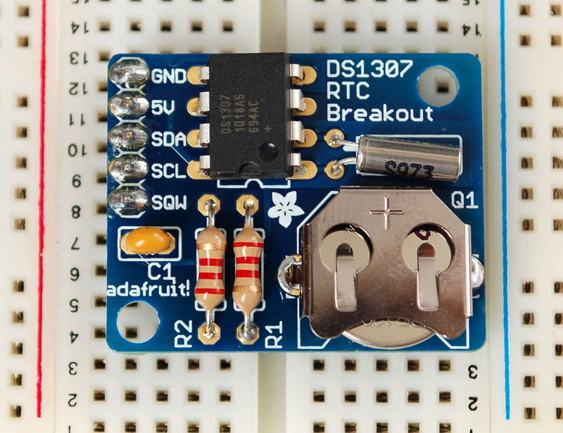
#define DS1307_ADDRESS 0x68
##
Using Solderable breadboards - Off-board Connections
BPS AN0002 Introducing Solderable PC BreadBoard
Here are some suggestions for connecting power and other off-board signal connections to a solderable PC breadboard:
- Use stranded 22 AWG wire for wire connections running off-board to other boards or devices. Solid 22 AWG wire will crack and break after being flexed many times. Stranded wire can be flexed more times.
- Use a strain relief to keep the wire from flexing at the point where it is soldered. Solder will wick up stranded wire when it is soldered, and make it stiff and susceptible to cracking. Using a strain relief causes the wire to flex away from the solder joint, where it is more flexible.
- Use headers or other connectors with removable plugs for off-board
9/12 to 5v Regulations
Jumptuck - Voltage regulation with our friend the 7805

Electrolytic smoothing caps
- input - 0.33uF
-
output - 0.1uF
- Digikey - 0.1uF. Nichicon UVR1H0R1MDD CAP ALUM 0.1UF 50V 20% RADIAL
- Digikey - 0.33uf. Nichicon UVR1HR33MDD CAP ALUM 0.33UF 50V 20% RADIA
JST PH connectors
Digikey - JST Sales America Inc B2B-PH-K-S(LF)(SN) CONN HEADER PH TOP 2POS 2MM
27 January 2014 » Arduino Parts
Arduino boards
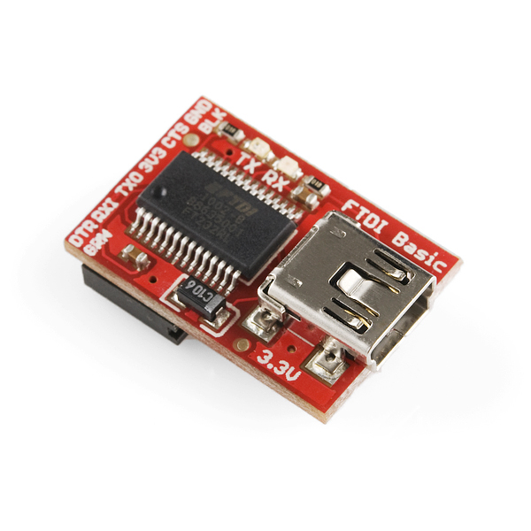
FTDI cabling
FTDI Friend + extras - v1.0 $14.75
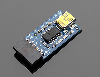
FTDI Basic Breakout - 3.3V $15.00
FTDI Basic Breakout - 5V $15.00
27 January 2014 » USB Cables
Spartfun - USB Buying Guide
What Does USB Do?
USB cables replace the huge variety of connectors that used to be standard for computer peripherals: Parallel ports, DB9 Serial, keyboard and mouse ports, joystick and midi ports… Really, it was getting out of hand. USB simplifies the process of installing and replacing hardware by making all communications adhere to a serial standard which takes place on a twisted pair data cable and identifies the device that’s connected. When you add the power and ground connections, you’re left with a simple 4-conductor cable that’s inexpensive to make and easy to stow.

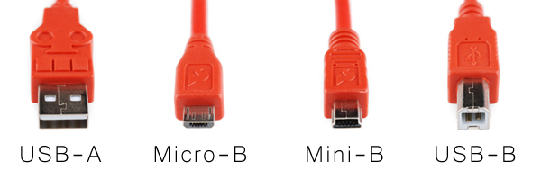
What Kinds of Cables are Out There?
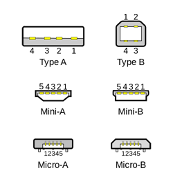
99% of host controllers will have a USB-A receptacle, so when you’re looking for a USB cable, you’ll usually be looking for a “USB A-to-something” cable. A lot of the time the USB-A end is assumed, since that’s the connector on most PCs, and cables will be named after the connector on the opposite end. Some smaller hosts use a Mini or Micro receptacle but they usually supply a pigtail adapter to USB-A.
Tags
- linux
- debian
- diy
- arduino
- cellphone
- turntable
- antenna
- diy_audio
- led
- rune_audio
- tuner
- chipamp
- raspberry_pi
- bluehost
- am
- mpd
- developers_to_watch
- beaglebone
- stereo_system
- headphone_amp
- i3wm
- fm
- arch_linux
- bluetooth
- nas
- preamp
- git
- javascript
- sql
- ti_cc_3000
- wifi
- reactor_safety
- volumio
- raspbian
- pptp
- Debian
- keyboard
- portable
- lp_storage
- firefox_phone
- firefox_os
- repair
- radio
- moteino_home_automation
- xmonad
- gitlab
- rails
- rails-api
- windows_os
- vm_host
- virtualbox
- electronics
- cubox
- rhombic_antenna
- diy_li_ion_battery_pack
- survival
- music_player
- headphones
- robotics
- welcome
- speaker
- subwoofer
- tear_drop_trailers
- philips_cd935
- diy_cabling
- laptop
- pickup
- hurricane_lantern
- coding
- cd_player
- bluez
- programming
- headset
- hardware_hackers
- arduino_ide
- tube_audio
- porch_steps_led
- ebay
- fm_transmitter
- coax_power_plug
- recipe
- vpn
- arduino_radio
- tv
- gammu
- stereo_receiver
- seamonkey
- thunderbird
- vinyl_lp
- cleaning
- hardware
- rs232
- max232
- gogs
- job_hunt
- phusion_passenger
- tuned_loop
- firefox
- icemonkey
- job_skills
- webmail
- spam_assassin
- irc
- security
- pc_audio
- green_chile
- moosefet
- usb
- ajax